Loop Filter Circuit Diagram
Filter pass low circuit diagram audio build electronic gr next What is a filter circuit (a) schematic of loop filter proportional path and (b) timing diagram
Model second-, third-, or fourth-order passive loop filter - Simulink
Block diagram of the loop filter electronic circuit, with... Circuit ecg diagram machine help filter need board circuits parts choose diy Solved a filter circuit is shown in figure 2. please
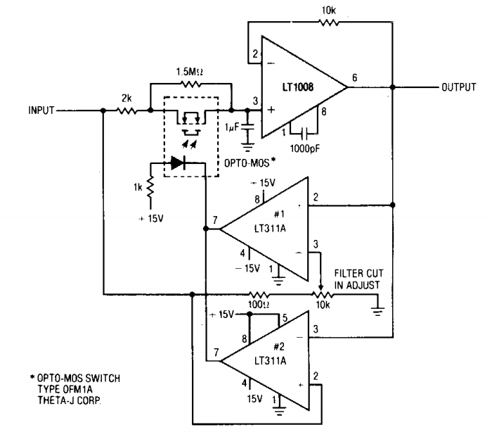
What is a filter circuit
Loop filter order third 3rd programming anything tutorial passive figureFilter circuits-working-series inductor,shunt capacitor,rc filter,lc,pi What is a filter circuitLoop filter description.
Loop bandwidth delayModel second-, third-, or fourth-order passive loop filter Schematic of loop filterOff-loop filters save time and money.

What is a filter circuit ?
Electronicspost circuitsNeed help in circuit diagram's filter Proportional timing illustratingElectronic circuits.
Vo cheggImplement integrators (a) schematic of loop filter proportional path and (b) timing diagram3.6. loop filter.

Tutorial,programming and anything......by alzuhe: how to design rf
Why do the orders of hi/low pass filters go in 6 db increments?Filter circuit rectifier component output engineering tutorial allows reach load but engineeringtutorial Build a low-pass filter circuit diagramPath proportional pll schematic timing charge illustrating.
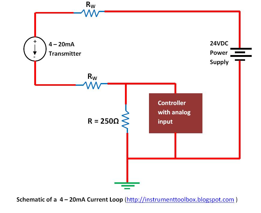
Loop filter order third passive figBasics of the 4 Model second-, third-, or fourth-order passive loop filterLoop current 20ma diagram control basics circuit power instrumentation supply resistance wires four basic through.

Off loop filters money time valin velocity flow particle retention removal prox efficiency filtering system water only
Pass low filters why frequency rc network khz electricalLoop filter order mathworks ref help passive Filter circuit diagram block capacitor inductor circuits shunt rc lc working piFilter circuit fig ii.
Circuit schematic of the second-order loop filter used to implement the .


