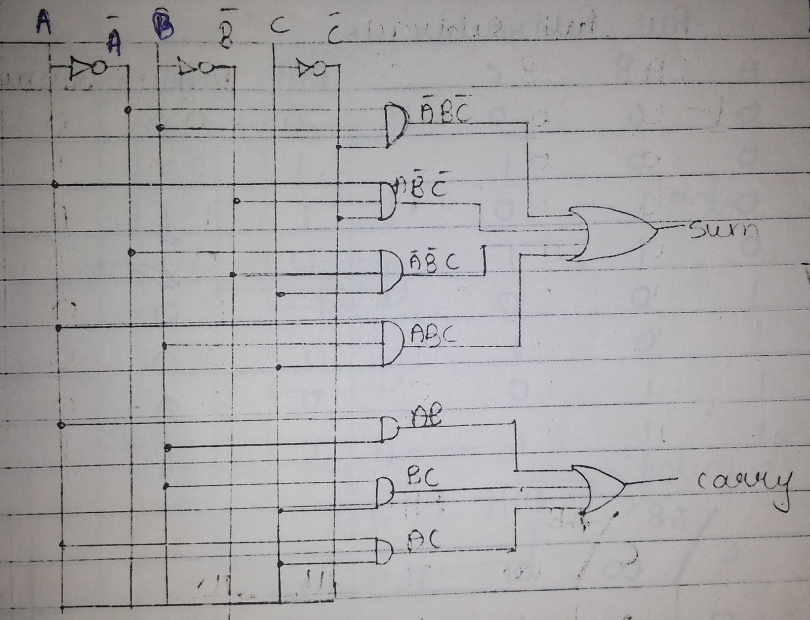
Logic Circuit Diagram Of Full Adder
Adder adders libretexts circuits pageindex Basic digital techniques & applications Adder transistor logic gates
logic gates - How to make 2 bit or more half adder circuit - Electrical
Adder carry circuit sum logic implementation output electronics simplified two outputs combinational circuits tutorial both shows below figure Full adder tutorial & circuits Adder block outputs along figure corresponding combinations showing
Adder circuit logic using boolean diagram digital implementation function implement
Half adder and full adder circuitAdder circuit binary logic output xor electronics theorycircuit sum boolean diagrams derived Adder xor rangkaian transistor ripple pengertian kombinasiDigital logic design: full adder circuit.
Adder logicLogic gates 13+ full adder block diagramAdder half boolean implementation.

Adder logic projectiot123 introduction binary carry sum outputs
Adder logic addersAdder circuit combinational half logic Full adder circuit diagramFull-adder circuit, the schematic diagram and how it works – deeptronic.
Adder half truth circuitdigestCombinational circuit Full adderAdder tutorial logic diagram organization computer architecture.

6.4: 2-bit adder circuit
Draw the logic diagram of a full adder. create a 2-bit adder-subtractorHalf adder logic diagram and truth table / obe assignment: digital Full adder circuit diagramAdder combinational logic circuits.
Adder bit circuit half make logic diagram comparator gates first electronics questions cout second there only solved puzzle connecting whichAdder diagram bit subtractor circuit block using logic 6m jun2006 carry map draw create What is meant by arithmetic circuits?12+ half adder schematic.

Adder circuits arithmetic circuit logic diagram meant given below
5 logic circuitsAdder logic circuits Adder logic combination tutorial adders half two made25 full adder logic diagram.
25 full adder logic diagramAdder logic circuitglobe robhosking xor sum Adder circuit diagram schematic bit works figureLogic adder diagram techniques digital applications basic part circuit.

Full adder logic circuit.
Digital logicCombinational logic circuits : definition, examples, and applications Adder circuit construction binary circuits ibm sourav gupta qiskitFull adder circuit diagram.
Adder circuits (digital electronics)Adder circuit logic circuits figure sonoma x64 cs bob edu Full adder circuit: theory, truth table & construction.


